| Issue |
Natl Sci Open
Volume 3, Number 5, 2024
Special Topic: Microwave Vision and SAR 3D Imaging
|
|
|---|---|---|
| Article Number | 20240009 | |
| Number of page(s) | 31 | |
| Section | Information Sciences | |
| DOI | https://doi.org/10.1360/nso/20240009 | |
| Published online | 19 July 2024 | |
REVIEW
Advances and prospects in SAR microwave vision three-dimensional imaging
1
National Key Laboratory of Microwave Imaging, Aerospace Information Research Institute, Chinese Academy of Sciences, Beijing 100190, China
2
School of Electronic, Electrical and Communication Engineering, University of Chinese Academy of Sciences, Beijing 100094, China
3
Key Laboratory of Intelligent Aerospace Big Data Application Technology, Suzhou 215123, China
* Corresponding authors (emails: This email address is being protected from spambots. You need JavaScript enabled to view it.
(Xiaolan Qiu); This email address is being protected from spambots. You need JavaScript enabled to view it.
(Chibiao Ding))
Received:
17
March
2024
Revised:
6
June
2024
Accepted:
2
July
2024
Abstract
Synthetic Aperture Radar three-dimensional (3D) imaging enables the acquisition of more comprehensive information, making it a recent hotspot in radar imaging. Traditional 3D imaging methods have evolved from 2D and interferometric imaging, combining elevation aperture extension with signal processing techniques. Limitations such as long acquisition or complex system from its imaging mechanism restrict its application. In recent years, rapid development of artificial intelligence has led to a swift advancement in radar, injecting new vitality into SAR 3D imaging. SAR microwave vision 3D imaging theory, which is built upon advanced technologies, has emerged as a new interdisciplinary field for radar imaging. This paper reviews SAR 3D imaging’s history and present situation, and introduces SAR microwave vision. We establish a theoretical framework covering representation models, computational models, processing paradigms and evaluation systems. Additionally, our research progress in this area is discussed, along with future prospects for SAR microwave vision 3D imaging.
Key words: SAR / microwave vision / 3D imaging / visual semantics / scattering mechanism
© The Author(s) 2024. Published by Science Press and EDP Sciences.
 This is an Open Access article distributed under the terms of the Creative Commons Attribution License (https://creativecommons.org/licenses/by/4.0), which permits unrestricted use, distribution, and reproduction in any medium, provided the original work is properly cited.
INTRODUCTION
Current status of SAR imaging: From 2D to 3D
Synthetic Aperture Radar (SAR), as an active microwave sensing technology, enables all-weather and all-day earth observation imaging. It plays an irreplaceable role in applications such as terrain mapping, disaster response, and smart cities. Traditional SAR imaging produces two-dimensional images, representing the projection of the three-dimensional physical reality onto a two-dimensional imaging plane. Due to the isometric projection nature of SAR imaging, issues such as perspective distortion and layover exist, significantly affecting its widespread application [1].
To address these challenges, researchers worldwide have proposed imaging systems such as Interferometric SAR (InSAR) and Stereo SAR, aiming to reconstruct stereo images of observed scenes using two images from different viewing angles [2,3]. InSAR utilizes the phase difference observed at two different elevation angles to reconstruct height information, while Stereo SAR, also known as radar photogrammetry, employs concepts similar to optical image disparity to calculate the three-dimensional position of targets using the range-Doppler equation. However, these approaches face difficulties in resolving the layover phenomenon [4]. In practical remote sensing applications, areas with steep terrain changes, such as mountains and urban environments, often experience significant layover issues. Both InSAR and Stereo SAR, inherently, provide a form of 2.5D imaging, unable to distinguish multiple scatterers affected by layover, thus limiting their application in urban and mountainous regions [5,6].
To overcome this limitation, the U.S. Naval Research Laboratory proposed the concept of SAR 3D imaging using elevation synthetic aperture in 1995. That same year, European Microwave Signal Laboratory (EMSL) achieved the resolution of two overlapping metal spheres using eight-track observations, marking a leap from theory to practice for SAR 3D imaging [7]. Following this breakthrough, numerous research institutions and researchers worldwide have conducted extensive studies. Currently, two main approaches have emerged: the first involves repeated flights for data acquisition called Tomographic SAR, and the second utilizes a single flight with a multi-channel array for data acquisition called Arrayed Interferometric SAR [8].
In the case of Tomographic SAR, both airborne and spaceborne platforms have been utilized in experiments globally, confirming the feasibility and effectiveness of this approach. The German Aerospace Center conducted multiple TomoSAR data acquisition experiments using its airborne E-SAR and F-SAR systems, achieving 3D imaging in forested areas and successfully distinguishing tree canopies, vehicles beneath the canopy, and terrain [9]. In China, the Institute of Electronics, Chinese Academy of Sciences, conducted the first airborne TomoSAR data acquisition experiment in 2013 [8]. On the spaceborne side, the University of Naples in Italy used ERS satellite data collected between 1992 and 1998 to obtain the first results of spaceborne TomoSAR experiments in the Naples region in 2005 [10,11]. In 2010, the German Aerospace Center used TerraSAR-X satellite data collected over more than a year to achieve high-resolution 3D imaging results in complex urban areas [12]. In 2013, the University of Pisa in Italy conducted TomoSAR 3D imaging experiments using 28 repeated Cosmo-Skymed satellite images [13]. In China, institutions such as the Aerospace Information Research Institute, Chinese Academy of Sciences and universities like Nanjing University of Aeronautics and Astronautics used high-resolution images from domestic satellites like GF-3 to achieve 3D reconstruction, demonstrating the potential of domestic satellites for 3D imaging [14].
As for Array Interferometric SAR, in 2004, the French Aerospace Lab (ONERA) developed an unmanned aerial vehicle (UAV)-borne downward-looking array 3D SAR system called the DRIVE system. This system employed a 12-transmitter, 12-receiver array radar for data acquisition [15–17]. In 2005, the German FGAN also developed a UAV-borne downward-looking array 3D SAR system named ARTINO, using a 44-transmitter, 32-receiver array with a total of 1408 equivalent channels for data acquisition [18–20]. However, detailed 3D imaging results from these two radar systems have not been publicly disclosed to date. Downward-looking array 3D imaging, due to its use of a nadir observation configuration, faces challenges of ambiguity in the cross-track direction. In 2015, the Institute of Electronics, Chinese Academy of Sciences, used an aircraft platform carrying a 2-transmitter, 8-receiver array antenna, employing a side-looking observation mode to achieve SAR 3D imaging over large scenes [21]. This achievement marked the world’s first Array Interferometric SAR 3D imaging results.
Challenges in 3D SAR imaging
A comprehensive analysis of the two current 3D imaging systems, namely Tomographic SAR and Array Interferometric SAR, utilizes multiple-angle observations in the elevation direction to construct synthetic aperture. In terms of information sources, they rely on the phase difference information provided by spatially diverse observations. In terms of processing modes, the focus is primarily on isolating processing for each pixel of the 2D SAR image. These factors collectively contribute to the significant requirement for a large number of multi-angle SAR images in the current 3D SAR imaging process.
For Tomographic SAR, this necessitates a large number of repeated flight trajectories, leading to a high volume of data acquisition, extended data acquisition cycles, and consequently, high time costs. In the case of Array Interferometric SAR, the requirement for a large number of channels in the array interferometric SAR system results in high economic costs and system complexity. These challenges have become the primary obstacles in the widespread application and promotion of 3D SAR imaging.
Development trends
To address the aforementioned challenges and reduce the time and economic costs associated with SAR 3D imaging, it is important to reevaluate the issue from the essence of 3D imaging. SAR 3D imaging primarily tackles the inverse problem of deducing the three-dimensional characteristics of objects from the information contained in the echo signals. The more comprehensive the information extracted from the echo signals, the smaller the solution space, and the higher the reconstruction accuracy. Considering the current challenges in 3D imaging, a key conclusion can be drawn. The fundamental reason for the high cost of SAR 3D imaging lies in the underutilization of information within the echo data. Analysis reveals that SAR echo signals contain rich information. From the perspective of information types, echo signals encompass multidimensional electromagnetic scattering information, while SAR images contain geometric structural information of targets.
In recent years, the advancement of computer technology and increased hardware computing power have spurred the emergence of new technologies capable of supporting the extraction of electromagnetic scattering information from echo signals and the extraction of semantic information from target images. Specifically, the rapid development of computational electromagnetics and computer vision has provided new perspectives for SAR 3D imaging.
Current SAR 3D imaging has not fully integrated microwave characteristics and image semantics, failing to efficiently utilize both microwave scattering information and visual information from the images. However, integrating these advanced technical means with traditional imaging poses significant challenges. The core difficulties lie in two aspects. The first is how to extract information favorable for 3D imaging from computational electromagnetics and computer vision. The second is how to incorporate the unstructured, qualitative information into existing frameworks based on current SAR 3D imaging geometry. SAR Microwave Vision 3D imaging theory provides answers to these challenges.
In the following sections of this paper, we will provide a detailed explanation of the conceptual connotations and theoretical framework of SAR microwave vision 3D imaging. In terms of conceptual connotations, this includes relevant definitions and core concepts, as well as a comparison with traditional 3D imaging theories. Regarding the theoretical framework, we will present its representation model, computational model and the processing paradigm. In Sections “Recent progress” and “Anticipated development trends”, recent progresses and future trends about SAR microwave vision 3D imaging are discussed.
CONCEPT AND CONNOTATION
Definition of SAR microwave vision 3D imaging
Synthetic Aperture Radar (SAR) microwave vision 3D imaging is a scientific methodology with the ultimate goal of achieving three-dimensional imaging. In this process, SAR, microwave, and vision are considered instrumental means. The scientific definition of SAR microwave vision 3D imaging involves the extraction of information conducive to three-dimensional imaging from SAR echo data and images through the application of microwave vision. This extracted information is organically integrated with the mathematical models of SAR 3D imaging to formulate computationally feasible models and methods. The overarching goal is to reduce dependence on the quantity of observations and enhance the precision of three-dimensional imaging [1].
The term microwave vision represents a form of physical intelligence, wherein physical intelligence combines a robust theoretical framework of physics to construct an intelligent system better suited to adapting to the physical world than humans. In the specific context of SAR 3D imaging, microwave vision aims to develop a form of physical intelligence that integrates microwave scattering mechanisms, computer vision, and relevant radar imaging theories. This integration is envisioned to better extract information conducive to three-dimensional imaging.
The information beneficial for 3D imaging is categorized in Table 1, where the first and second rows represent universally significant information for the entire scene, the third and fourth rows denote information relevant to typical large-scale and small-scale structures, and the last row mainly concerns about the microwave scattering mechanism of each pixel.
Information conducive to SAR 3D imaging
Core concepts in SAR microwave vision 3D imaging
3D SAR observation model
The 3D SAR observation model (Figure 1) refers to the construction of a 3D SAR imaging model using multi-channel observation data for elevation synthetic aperture. The three dimensions in 3D SAR imaging refer to range, azimuth, and elevation. The resolution in range and azimuth directions remains the same as in the original 2D SAR imaging. Range resolution is achieved through pulse compression by transmitting wide-bandwidth signals for high resolution, while azimuth resolution is obtained through platform motion forming synthetic aperture for resolution.
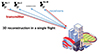 |
Figure 1 Schematic of SAR 3D imaging. |
SAR image semantic information
In the context of SAR microwave vision 3D imaging, SAR image semantic information refers to semantic details extractable from 2D SAR images using computer vision techniques (Figure 2) to assist in 3D imaging. In computer vision, image semantics generally denote the meaning of the image content, categorized hierarchically into different layers. Despite differences in imaging mechanisms between SAR and optical images, resulting in phenomena like layover and perspective contraction, SAR images still project the physical world onto a 2D plane. Structural information of target objects in 3D space is preserved in the 2D image. Specifically, for the purpose of SAR 3D imaging, the visual layer corresponds to geometric structural information of observed objects, focusing on aspects such as shapes and edges. The object layer corresponds to category information of observed objects, such as buildings, vehicles, etc. The conceptual layer corresponds to information at the entire image level, such as identifying whether the scene represents a mountainous or urban area. Information from the visual and object layers provides strong prior information for fine-grained targets, constraining the targets to their respective geometric structures. Semantic prior information from the conceptual layer guides the selection of processing methods, as different observation scenes benefit from different processing theories, such as sparse signal processing and spectrum estimation.
 |
Figure 2 Semantic information extracted from SAR images. (a) Building instance segmentation. (b) Clustering results. (c) Building model reconstruction. |
3D scattering mechanisms
The imaging characteristics of target scattering and its correlation with geometric and physical parameters such as shape and material, waveform parameters such as frequency and polarization, and observation conditions including incident angle and mode in SAR images are multifaceted. The 3D scattering mechanisms (Figure 3) involve the exploration of pixel-level scattering mechanisms in SAR images to provide fine-grained prior information for 3D imaging.
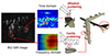 |
Figure 3 The 3D scattering mechanism from SAR images. |
Comparison
In this subsection, a comparison will be made from different perspectives between traditional SAR 3D imaging and SAR microwave vision 3D imaging, highlighting the distinctions in their imaging modalities.
Table 2 illustrates the similarities and differences between the existing SAR 3D imaging system and the proposed SAR microwave vision 3D imaging system in various dimensions. Both systems serve the same purpose of achieving 3D imaging. Therefore, they both implement three-dimensional imaging in the range-azimuth-elevation dimensions, and the geographic coordinates of the 3D images can be obtained through coordinate transformation.
In terms of the 3D resolution mechanism, both systems use a pulse compression technique with a transmitted wideband signal for range resolution and employ the synthetic aperture formed by the motion of the platform for azimuth resolution. For elevation resolution in traditional methods, it relies on multi-angle observations to construct a synthetic aperture. In contrast, SAR microwave vision 3D imaging achieves elevation resolution not only through multi-angle observations but also by utilizing semantic information extracted from SAR images and target scattering mechanism information. Thus, its elevation resolution mechanism is based on microwave vision theory.
Regarding the processing paradigm, traditional methods follow a single-direction open-loop approach with pixel-wise processing, isolating each pixel without considering spatial adjacency relationships between pixels. The process utilizes multi-channel 2D SAR images for signal processing to obtain 3D imaging results, representing a one-way processing flow. SAR microwave vision 3D imaging introduces a new processing paradigm, i.e., closed-loop feedback and neighborhood collaborative processing. Neighborhood collaborative processing involves the coordinated processing of multiple pixels defined in a generalized neighborhood. This paradigm shift leads to a qualitative leap in 3D imaging results. Closed-loop feedback means that the 3D imaging process does not end with obtaining results. Instead, the results are used to correct errors, extract semantic information, and derive scattering mechanism information in the processing flow, providing more accurate prior information constraints for the next round of 3D reconstruction.
The disciplinary foundations of the two systems also differ. Traditional methods primarily involve radar signal processing, whereas the proposed method is an interdisciplinary product that incorporates advanced techniques from computational electromagnetics and computer vision theory on the basis of radar signal processing.
Comparison between traditional and SAR microwave vision 3D imaging
THEORETICAL FRAMEWORK
The theoretical framework of SAR microwave vision 3D imaging is fundamentally about processing information from radar echo data to generate high-quality 3D images. Therefore, it involves addressing three challenges, namely the representation, computation, and processing of information. Thus, the theoretical framework of SAR microwave vision 3D imaging primarily encompasses the following components.
Representation model
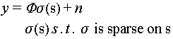
At the current stage, the two SAR 3D imaging methods, as described in the conceptual framework in previous section, are based on aperture synthesis in the elevation direction. Based on this concept, widely used 3D imaging model is as follows.
 (1)
(1)
In the above equation  , is the multi-channel observation vector, Φ is the sensing matrix,
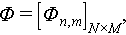
 In this model, the target scattering coefficients are considered to be sparsely distributed in the elevation direction.
This paper provides the new framework for SAR microwave vision 3D imaging as follows. It should be noted that SAR microwave vision 3D imaging utilizes multi-angle and multi-polarization observations, and the characterization framework incorporates the concept of holographic SAR proposed by the authors. For details on holographic SAR, please refer to the reference provided. Therefore, considering the holographic characteristics of the targets, the characterization model for SAR microwave vision 3D imaging is as follows:

 (2)
(2)
 is used to comprehensively consider the target’s holographic scattering characteristics for the sought scattering coefficients. The terms in parentheses represent dependencies on the radar system and target scattering characteristics. Specifically,
  represents the unit Jones vector indicating the polarization state of the electromagnetic field.
  is the carrier frequency.
  is the unit vector characterizing the direction of electromagnetic wave propagation.
  characterizes the moment of propagation.
  is the 3D position vector of the target and
  is the three-dimensional size of the target.
  and
and  are the frequency-dependent factor and the curvature-dependent factor, respectively.
  is the target’s positional vector relative to the radar, including pitch and azimuth angles.
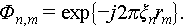
The lower part of this equation is the restrictions to be satisfied for the unknown vector  . Before going into detailed explanations, it is important to note that the presented expressions here are abstract representations. In practical applications, there are more specific and concrete forms. The provided analysis here offers a macroscopic perspective. The first constraint is the sparse distribution of the target’s scattering coefficients in 3D space. This is a constraint commonly employed in traditional SAR 3D imaging models.
  represents semantic constraints, including the correlation between scattering points at different locations. For example, whether two scattering points at different locations belong to the same target or the same type of terrain, and whether two scattering points at different locations have continuity in 3D space or not.
  represents constraints on the positions of scatterers and is primarily expressed in the form of spatial structure primitive functions.
  is the restrictions of scattering mechanism.
Computation model
Based on the traditional SAR 3D imaging representation model, existing computational models mainly focus on pure signal processing. As mentioned earlier, the increment of SAR microwave vision three-dimensional imaging lies in extracting more prior information from the echo signal and SAR images. To achieve this goal, this paper proposes an innovative computation model that integrates the extraction of three-dimensional information.
Specifically, based on the aforementioned representation model, this paper introduces two types of computational models. One type is based on sparse 3D imaging solution models, integrating the information obtained from microwave vision into the model in the form of explicit constraints. This includes semantic regularization models, spatial deterministic constraint models, spatial statistical constraint models, joint constraints of multi-dimensional observations, etc. Another type is built upon neural network models, training the network to learn microwave vision prior information, thus achieving the implicit feedback of microwave vision constraints.
Generally, the first type of model is based on compressed sensing theory, with additional explicit constraints. Taking the semantic regularization constraint model as an example, semantic regularization constraints include but are not limited to various types of neighborhood consistency under semantic segmentation, such as variational regularization, phase gradient, etc. Neighborhood continuity constraints, such as local elevation continuity and intra-class correlation after segmentation, are also considered. These constraints mainly take into account various similarity measures between pixels of the same type after semantic segmentation and use them as constraint conditions to improve the 3D imaging quality. The statistical and deterministic constraints of 3D positions directly infer the spatial distribution of scatterers from the perspective of 3D space distribution, using the aforementioned prior information to constrain the solution space.
The second type of model is based on neural networks to achieve the implicit feedback of microwave visual information. It combines sparse unfolding networks and deep learning networks to construct a heterogeneous neural network. On the one hand, it utilizes the network to extract microwave visual prior information. On the other hand, it trains to learn the feedback of prior information, achieving adaptive optimization of network parameters. Ultimately, it aims to combine the interpretability of signal processing with the intelligent extraction of microwave visual information.
Detailed explanations of these different computational models will be provided in the following section on research progress. This section provides a brief overview.
Processing paradigm
In Section “Concept and connotation”, it has been mentioned that the new and old theories exhibit significant differences in their processing approaches. The figure below provides a visual comparison for better understanding. Figure 4 illustrates a direct comparison between the two theories, highlighting their notable distinctions in processing methods.
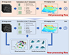 |
Figure 4 Paradigm of processing. |
The traditional method is a forward open-loop process, corresponding to the lower part of the diagram where the red dashed box is omitted. It mainly involves processing the 2D SAR image to obtain the final 3D result. In contrast, the proposed method in this paper adds the step of extracting 3D information by microwave vision. As shown in the diagram, 3D information is extracted from both 2D and 3D images, including but not limited to visual semantic information and scattering mechanism information. These pieces of information, based on multi-incident-angle observations, provides prior knowledge about the spatial distribution of scattering points, anticipating the location of the scattering points. Overall, the method proposed in this paper adopts a robust estimation-based iterative processing approach, progressively improving the 3D imaging results.
Evaluation criteria
To address the existing challenges of inconsistent evaluation criteria and the absence of a standardized assessment system for SAR 3D imaging methods, we have developed a comprehensive evaluation framework. This framework is designed to assess the effectiveness of 3D imaging applications from multiple perspectives, aiming at the promotion of SAR 3D imaging.
Generally, the evaluation system mainly considers the following key aspects. The first is spatial accuracy, which is used to examine the deviation of reconstructed scatterers in 3D imaging concerning the actual positions of the targets. The second is about scattering coefficient estimation. For this purpose, we mainly assess the precision of estimating target scattering coefficients, including amplitude, phase, and polarization characteristics. The third is the unwrapping capability, which aims to evaluate the resolution of 3D imaging by gauging its ability to unwrap and discriminate overlapping structures, addressing the most important challenge discussed earlier. Finally, we consider the overall performance, which mainly incorporates success rates in 3D imaging and 3D image entropy, constructing comprehensive evaluation metrics for a quantitative and integrated assessment of overall performance.
Three-dimensional position accuracy
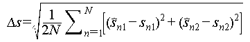
Regarding 3D position accuracy, evaluations are primarily conducted from three perspectives. The accuracy of the position of scatterers focuses on the 3D precision of individual scatterers, while the accuracy and completeness of the 3D point cloud primarily assess the overall accuracy of the target point cloud.
The definition of accuracy of the position of scatterers is as follows. Taking two overlapped scatterers as an example, the position accuracy of scatterers is given by the following formula:
 (3)
(3)
In equation (3)  and
and  are the position estimations of two scatterers,
  and
and  are the true positions. It is worth mentioning that
  ,
, ,
, ,
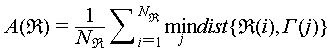
, are all values normalized by Rayleigh resolution. The accuracy and completeness are defined as follows [22]:
 (4)
(4)
 (5)
(5)
In above equations,  denotes the reconstructed 3D point cloud while
  is the high-precision reference ground truth.
  is the number of scatterers in reconstructed point cloud while
  is that for ground truth.
  is the distance between two scatterers. The above metrics can be quantitatively evaluated in simulations or cooperative target experiments with known positions to assess the performance of different algorithms in 3D reconstruction.
Scattering coefficients accuracy
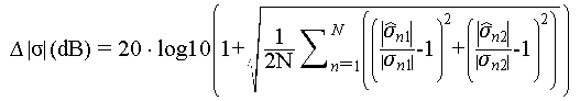
The accuracy of scattering coefficients mainly focuses on the amplitude and phase information of each scatterer after 3D reconstruction. These details are crucial for target recognition based on 3D point clouds and for 4D and 5D imaging processes that consider deformations. We propose three quantitative metrics to assess the accuracy of the scattering coefficients. The first is the accuracy of scattering intensity estimation.
 (6)
(6)
In equation (6),  ,
, are the reference intensities of the two overlapped scatterers, and
  ,
, are the estimated intensities of the two overlapped scatterers.
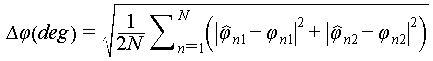
The accuracy of phase estimation is defined as follows:
 (7)
(7)
In equation (7),  and
and  are the estimated phases of the two overlapped scatterers, and
  and
and  are the ground truths.
The output signal to noise level of 3D imaging result comprehensively considers the accuracy of both scattering intensity and phase estimation. Taking two overlapping points as an example, the output SNR level is as follows:
 (8)
(8)
 is a complex vector and each element stands for the complex scattering coefficient.
  is the Euclidean norm.
3D imaging resolution
As the two-dimensional SAR image achieves range and azimuth resolution through pulse compression and azimuth synthetic aperture, the 3D imaging resolution here primarily focuses on the resolution capability in the third dimension. It is defined as the distance between overlapping points where the success rate is greater than 50%, considering a given signal-to-noise ratio. This can serve as an indicator for assessing the 3D resolution.
Comprehensive evaluation
The above three dimensions have been analyzed from multiple perspectives. In order to comprehensively evaluate the performance of 3D imaging, this paper summarizes the comprehensive evaluation indicators for 3D imaging, namely the success rate of 3D imaging and the 3D image entropy.
The success rate comprehensively considers the position accuracy of scatterers and the signal-to-noise ratio of the imaging output. In simulations, the success rate is calculated by statistically determining the proportion of points with position accuracy and output signal-to-noise ratio exceeding a predefined threshold among the total points.
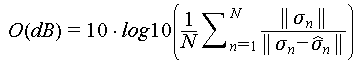
As for the 3D entropy, it quantifies the amplitude of pixel values after 3D imaging, usually 8-bit grayscale quantization, then calculates the grayscale histogram and the compute entropy. The formula is as follows [23]:
 (9)
(9)
 (10)
(10)
The 3D image entropy is an extension of 2D image entropy into 3D space, which can indirectly reflect the sharpness of 3D image. The sharper the 3D image, the smaller the value. It provides an evaluation metric consistent with human visual perception.
These aspects collectively contribute to a thorough evaluation of the effectiveness and reliability of SAR 3D imaging methodologies.
RECENT PROGRESS
The SAR microwave vision 3D imaging theoretical approach is not only innovative in 3D imaging processing methods but also encompasses both hardware system design and development, as well as information extraction and processing. In summary, it involves a balanced consideration of both hardware and software aspects. Therefore, this chapter will provide an overview of the progress made by our team in the field of microwave vision SAR 3D imaging. It will cover the theoretical framework, SAR microwave vision 3D imaging algorithms, as well as our self-developed SAR microwave vision 3D imaging system and dataset.
Theoretical framework and fundamental imaging model
In 2019, we systematically reviewed the development of SAR 3D imaging technology, conducting an in-depth analysis of the characteristics of existing SAR 3D imaging techniques [1]. We identified the untapped 3D information inherent in SAR echoes and images. For the first time, we introduced the new concept and approach of SAR microwave vision 3D imaging (Figure 5), which is a combination of microwave scattering mechanisms and image visual semantics. This fusion establishes the theoretical framework and methodology for SAR microwave vision 3D imaging, aiming to achieve efficient and cost-effective SAR 3D imaging. We first emphasized the concepts, objectives, and key scientific issues of SAR microwave vision 3D imaging, presenting initial technical approaches that offer novel perspectives for SAR 3D imaging.
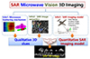 |
Figure 5 Diagrammatic sketch of microwave vision SAR 3D imaging. |
Following the proposal of the concept, we established an accurate SAR 3D imaging model. The planar-wavefront-based TomoSAR imaging model introduces significant approximation error when applied to the low-altitude airborne platform. This will lead to significant height error of reconstructed infrastructures. In order to circumvent the aforementioned problem, we propose spherical-wave-front models with the exact form or an approximate form of the slant range formula [24]. This model is strictly built upon the spherical wave propagation model of electromagnetic waves, applicable to various application scenarios, whether in the far-field of near-field case. The proposed model has been adopted in our UAV based array InSAR experiment, demonstrating its efficacy. In contrast to the imaging model based on the conventional planar wave-front approximation, the reconstructed point cloud of a 69.2-meter-high building introduced a height error of approximately 10 meters due to the model’s limitations. However, utilizing our proposed precise model eliminates errors introduced by the model itself, resulting in the extracted 3D model consistent with the actual target. Figure 6 depicts the diagrammatic sketch of the proposed model and comparison between results by classical and proposed model. It is worth mentioning that this model transforms the third dimension from elevation to off-nadir angle, which provides a new research perspective for subsequent studies.
 |
Figure 6 Spherical SAR 3D imaging model and comparison between different models. (a) Planar wavefront model. (b) Spherical wavefront model. (c) Reconstruction results by different models. |
Except the approximation error induced by planar-wave-front model, in the airborne near-field case, there will exist channel migration among all channels. Existing methods for 3D imaging in TomoSAR often assume that the layover remains consistent across different channels. In low-altitude airborne scenarios, the variability of the range from the same layover to different channels becomes significant and cannot be ignored even after co-registration. Thus, we study on the phenomenon of channel migration (CM) in sparse TomoSAR under low-altitude conditions. We derive a model for the differential range, which describes the variation in range from a specific target to different antennas [25]. To address the CM issue, we propose the application of the keystone transform (KT) along the array axis, effectively correcting for the channel migration. We can subsequently apply compressed sensing-based 3D imaging methods to obtain accurate and reliable 3D reconstruction results. To validate the effectiveness, we conduct experiments using both simulated data and real data acquired by the MV3DSAR system, a drone-borne TomoSAR system which will be introduced in the following. Figure 7 presents the model and results regarding this issue. The results demonstrate that our proposed method offers a more precise solution to the challenging problem of reconstructing low-altitude sparse TomoSAR data. Overall, our study is the first time that has addressed channel migration and has contributed to the advancement of 3D imaging in urban environments.
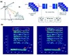 |
Figure 7 Models and results. (a) Flowchart of channel-migration correction. (b) Results before and after CM. |
SAR MV 3D imaging algorithms
SAR 3D imaging algorithm optimization
After imaging model construction, we conducted a series of studies regarding SAR microwave vision 3D imaging algorithms, which address high accuracy, combination with geometric semantics, combination with microwave scattering mechanisms and so on. Details are as follows.
In the classic compressed sensing algorithm process, it is necessary to divide continuous elevation directions into fixed grids and assume that the target is exactly on the divided grids. Nevertheless, this assumption is often difficult to establish, leading to off-grid effect, which is currently rarely discussed in TomoSAR. We discussed the TomoSAR observation model with off-grid targets, and proposed a solution model that uses an additive perturbation term to correct the impact of target deviation from the grid. On this basis, a combination of local optimization algorithm and L1 norm minimization is introduced to solve the proposed off-grid TomoSAR model [26]. Figure 8 illustrates the comparison between the proposed algorithm and the classical method based on L1 norm minimization both on simulation data and airborne array interference SAR real flight data. It turns out that for the off-grid target, the proposed method can obtain more precise position, amplitude and phase solution results, proving the superiority of the method.
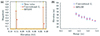 |
Figure 8 Off-grid TomoSAR imaging method. (a) Magnitude estimation performance. (b) Elevation estimation performance. |
Furthermore, the TomoSAR model in sparse scenes can be regarded as a single snapshot line spectrum estimation problem, while the existing methods are either limited in accuracy due to the off-grid effect or high computational complexity. We proved that its least square objective function under the condition of a single snapshot is analytical and convex within the neighborhood of the true value [27]. Gradient descent algorithm can be adopted to solve the above function iteratively and effectively. Numerical simulations for evenly distributed antenna array case show that the proposed GDLS algorithm avoids the off-grid problem with a minor amount of computation, improving the estimation accuracy at a lower cost. The figures show a comparison between the proposed method and the classical CS algorithm. We projected the estimating point clouds for real data to the range elevation plane (Figure 9). Our method exhibits higher estimation accuracy and stronger resolution capability, providing a point cloud with better performance free from off-grid errors.
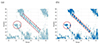 |
Figure 9 Side view of reconstruction result in radar geometry by traditional method and GDLS. (a) Traditional method. (b) Proposed GDLS method. |
Although the GDLS algorithm can provide better point cloud, treating the elevation resolution as a line spectrum estimation problem poses challenges for traditional super-resolution spectrum estimation algorithms, which necessitate multiple snapshots and uncorrelated targets. Meanwhile, compressed sensing (CS)-based methods, widely used in modern TomoSAR imaging, encounter the gridding mismatch effect, significantly compromising imaging performance. In addressing these issues, we introduced an enhanced fast atomic norm minimization (ANM) algorithm for TomoSAR elevation focusing, namely the IVDST-ANM algorithm. This approach mitigates the substantial computational complexity associated with conventional time-consuming semi-positive definite programming (SDP) by employing the iterative Vandermonde decomposition and shrinkage-thresholding (IVDST) method. Importantly, it preserves the advantages of ANM, including gridless imaging and the capability of single snapshot recovery. The effectiveness of the proposed method is demonstrated through numerical performance evaluations using simulated data and the reconstruction results of an urban area from the SARMV3D-Imaging 1.0 dataset (Figure 10) [28].
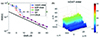 |
Figure 10 Performance comparison of IVDST-ANM and other state-of-art technology, and reconstruction result of urban areas. (a) RMSE versus SNR by different method. (b) Reconstructed point cloud by IVDST-ANM. |
SAR visual semantics extraction
Buildings are one of the typical targets in urban remote sensing images, and the extraction of buildings from remote sensing images finds extensive applications. Semantic segmentation of buildings is a crucial task and prerequisite for realizing SAR microwave vision 3D imaging. In the optical remote sensing domain, significant progress has been made in the semantic segmentation of buildings. However, in the Synthetic Aperture Radar (SAR) domain, challenges persist due to SAR imaging characteristics such as layover, foreshortening, and shadows. We addressed these challenges by proposing a novel complex-valued convolutional and multi-feature fusion network (CVCMFF Net, Figure 11) for building semantic segmentation in SAR images [29]. To make better use of SAR image information, equivalent complex-valued convolution layer and equivalent complex-valued pooling layer were incorporated into the network to accommodate the input complex data. Considering the diverse shapes and sizes of buildings, an atrous spatial pyramid pooling (ASPP) method was introduced for multiscale feature fusion. The network also integrated a multichannel feature fusion module to jointly process the master SLC image, slave SLC image, and interferometric phase image. Cross entropy (CE) was employed to quantify the disparities between the actual distribution and the predicted model distribution. The loss was determined by the sum of cross entropy for all pixels. The network was trained on a simulated dataset and demonstrated favorable inference results on measured datasets.
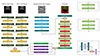 |
Figure 11 Network structure and segmentation result of CVCMFF Net. |
Except extracting the building structures from the two-dimensional SAR images, we have explored the chance to obtain the 3D clues from the point cloud [30]. Due to issues such as the scattering characteristics of ground objects, system noise, baseline measurement errors, etc., traditional TomoSAR inversion methods often encounter the following problems in the obtained point clouds. The first is sparsity or the absence of spatial points corresponding to partial structures, making it insufficient to represent their complete structures. The second is deviations from real structures or the presence of a significant amount of noise points. To address these challenges, Wang and collaborators propose a progressive building facade detection algorithm based on structural priors [30]. The algorithm initially projects the initial array InSAR spatial points onto the ground to generate connected regions corresponding to the building facade. It then progressively detects potential line segments within each connected region guided by structural priors, subsequently generating the corresponding building facade based on the detected line segments and their associated spatial points. During this process, the detection space of line segments corresponding to the current connected region is constructed based on the detected line segments in its adjacent connected regions, effectively ensuring overall efficiency and reliability. Experimental results are summarized in Figure 12 and demonstrate that the proposed algorithm can rapidly detect numerous reliable building facades from massive, noisy array InSAR spatial points, effectively overcoming the drawbacks of traditional multi-model fitting algorithms in terms of low efficiency and reliability.
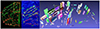 |
Figure 12 Intermediate results of line and plane detection results. |
SAR 3D imaging algorithms with semantics constraints
In SAR image semantics, the most prominent contribution to 3D imaging is the geometric structural information of the targets (Figure 13). This approach relies on the premise that SAR images and 3D point clouds are mappings of the real-world physical environment. The geometric structures present in 2D images exhibit similar representations in 3D point clouds.
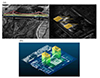 |
Figure 13 Geometric constraint SAR 3D imaging. (a) Geometrical structures from SAR images. (b) Co-registered SAR and lidar point cloud. |
Based on above analysis, we propose a 3D imaging method based on deterministic constraints using spatial structural elements. This approach primarily addresses the challenge of high clutter in current SAR 3D imaging under low signal-to-noise ratio conditions. By leveraging geometric structural elements provided by semantic information in SAR images, the method constrains the positions of scatterers in the reconstructed 3D point cloud. The approach relies on SAR 3D imaging geometric models and extracted target geometric structures. It adaptively constrains the solution space based on information such as image signal-to-noise ratio, effectively suppressing clutter points. Experimental data validation demonstrates that this method significantly reduces clutter points, enhancing the quality of 3D imaging [31].
The aforementioned deterministic approach is for geometric constraint SAR 3D imaging. We also explored a 3D imaging method based on statistical constraints using spatial structural elements, considering both large and small scales. The models are presented in Figure 14. This approach involves probabilistic modeling of the spatial distribution of scatter points in the 3D point cloud based on geometric semantic information, offering greater flexibility compared to deterministic constraints. For large-scale processing targeting linear and planar structures, scatter points corresponding to these structures are modeled using a generalized Gaussian distribution, solved through maximum likelihood estimation. In small-scale processing, each pixel and its neighborhood are considered [31]. Addressing the limitation of pixel-wise processing, which neglects spatial adjacency, this method employs a local Gaussian Markov random field to model the spatial distribution of scatter points in the neighborhood. Adaptive constraint solutions are achieved based on signal-to-noise ratio and the correlation between observation vectors. These methods produce high-quality 3D imaging results with limited observations, effectively incorporating geometric semantic information from SAR images. Inspired by this approach, we further expand the usage of geometric constraints in stereo SAR 3D imaging. A novel solution for stereo 3D localization combined with geometric semantic constraints is proposed and validated on spaceborne SAR data.
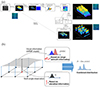 |
Figure 14 Geometric constraint SAR 3D imaging based on statistical model. (a) Large-scale case. (b) Small-scale case. |
In addition, we propose a novel tomographic SAR 3D imaging method based on sparse and low-rank structures. Traditional tomographic SAR imaging, relying on compressed sensing, only sparsely represents and reconstructs the elevation dimension for given azimuth-range cells. Our method recognizes the similar layout distribution in urban and forest areas, where targets in adjacent azimuth-range cells exhibit strong correlation in their elevation distribution. By incorporating the Karhunen-Loeve transform, our approach captures the low-rank characteristics of elevation distribution across neighboring azimuth-range cells. This results in a combined sparse and low-rank structured model for tomographic SAR imaging of target areas. We employ the ADMM (Alternating Direction Method of Multipliers) algorithm to solve this imaging model. The complex original optimization problem is decomposed into simpler sub-problems, which are then iteratively projected through alternating optimization variables, yielding the tomographic SAR imaging result. This method enhances reconstruction accuracy under scenarios of low overflights or channel counts, demonstrating superior imaging performance [32].
Except the urban areas, we explored the application of proposed method in mountainous areas. The predominant focus of TomoSAR in 3D reconstruction has been on low-lying targets, with limited literature addressing the reconstruction of 3D mountainous terrain. Surveying high mountain areas remains challenging due to the layover phenomenon. Therefore, conducting research on 3D mountain reconstruction using airborne array TomoSAR holds significant value. Nevertheless, the original TomoSAR mountain point cloud encounters elevation ambiguity issues. Additionally, in mountains with intricate terrain, points at different elevations may intersect, intensifying the complexity of the problem. We introduce a novel method for resolving elevation ambiguity based on the continuity of mountain structures. Initially, Density-Based Spatial Clustering of Applications with Noise (DBSCAN) and Gaussian Mixture Model (GMM) are combined for point cloud segmentation [33]. DBSCAN ensures coarse segmentation based on density, while GMM enables fine segmentation of abnormal categories resulting from intersections. Subsequently, the segmentation results are reorganized along the elevation direction to reconstruct all potential point clouds. Finally, the real point cloud is automatically extracted within the constraints of boundary and elevation continuity (Figure 15). The efficacy of the proposed method showcases its potential for addressing challenges in 3D mountain reconstruction.
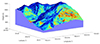 |
Figure 15 Reconstructed point cloud of mountainous areas based on proposed method. |
SAR 3D imaging algorithm with scattering mechanism
So far, 3D imaging methods have improved target localization accuracy but lack of the ability to distinguish various scattering mechanisms (SMs). In order to address this issue, we conducted a series of experiments using multi-baseline polarimetric coherence optimization and Pauli decomposition methods (Figure 16). They were used to establish digital elevation models (DEM) of the observed areas and preliminarily analyze SMs corresponding to real targets. Furthermore, we proposed a novel method based on maximizing polarimetric energy to enhance the 3D identification of targets. This method projects the original signal vector onto one component by rotating the polarization bases, ensuring optimal utilization for total polarimetric power. The projected signal vectors, derived from the above methods, are then treated as the input for subsequent height inversion. Eventually, we applied these methods in two sets of InSAR datasets from Fudan University, Shanghai, and Suzhou Aerospace Information Research Institute, Jiangsu. The results demonstrate that the 3D point clouds rendered by polarized parameters through Pauli decomposition and the new method display exceptional potential in retaining detailed structural information and distinguishing different scattering mechanisms. This improvement provides a research foundation for fully polarized array InSAR and TomoSAR.
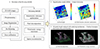 |
Figure 16 Pol-array-InSAR processing model and results. |
Neural network-based algorithms
The multi-channel circular trajectory SAR enables omnidirectional observation of targets, addressing the shadow issues associated with conventional TomoSAR 3D imaging along straight trajectories. However, conventional processing methods such as compressed sensing (CS) or back projection (BP) require a sufficiently large number of observations, leading to significant computational overhead in 3D imaging. To tackle these challenges, we proposed a sparse-aspects-completion network (SACNet, Figure 17) based on the Generative Adversarial Network (GAN) principle [34]. The approach involves selecting a sparse subset of aspect data from the acquired omnidirectional dataset and employing traditional methods for 3D imaging in each aspect, resulting in an incomplete point cloud of the target. Subsequently, these partial point clouds from selected aspects are input into SACNet, which outputs a complete 3D point cloud of the target. The innovative approach involves training a GAN to learn the underlying 3D structure of vehicles and subsequently generating detailed reconstructions. The technique effectively addresses the challenge of sparse data, providing a promising solution for accurate 3D vehicle reconstruction in SAR imagery.
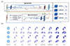 |
Figure 17 Network structure and 3D imaging results by different methods. (a) Network structure of SACNet. (b) Point cloud completion results. |
Similar to the InSAR technique, phase information is of crucial importance to SAR 3D imaging. The quality of interferometric phase significantly influences the effectiveness of the reconstruction. Therefore, interferometric phase filtering is crucial. Our team proposed an unsupervised convolutional neural network (CNN)-based method for denoising multi-channel interferometric phase data. A diagrammatic sketch of this method is shown in Figure 18. The focus of the study is on addressing the challenges in this area. The method utilizes a CNN to automatically learn and remove noise from multi-channel interferometric phase data, achieving denoising without the need for labeled training samples. This approach demonstrates effective denoising results, enhancing the accuracy of 3D reconstruction in TomoSAR [35].
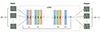 |
Figure 18 Diagrammatic sketch of proposed denoising CNN. |
CS-based algorithms have been incorporated into TomoSAR to leverage their super-resolution potential with limited samples. However, traditional CS-based methods face drawbacks, such as weak noise resistance, high computational complexity, and intricate parameter fine-tuning. In pursuit of efficient TomoSAR imaging, we present a novel sparse unfolding network, named Adaptive Threshold ALISTA-based Sparse Imaging Network (ATASI-Net), built upon the architecture of the analytic learned iterative shrinkage thresholding algorithm (ALISTA) with adaptive threshold [36]. The weight matrix in each layer of ATASI-Net is pre-computed as the solution of an off-line optimization problem, simplifying the training stage by requiring the learning of only two scalar parameters from data. Additionally, an adaptive threshold is introduced for each azimuth-range pixel, allowing not only layer-varied but also element-wise threshold shrinkage. Figure 19 illustrates the framework of the proposed ATASI-Net and the data flow of each module in the k-th layer, experimental comparison results with conventional algorithms, and visual outcomes of semantic feedback from SAR images.
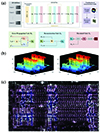 |
Figure 19 Details and performance of ATASI-Net. (a) Overall architecture of ATASI-Net and the data flow of each module. (b) Point cloud comparison results based on the traditional CS algorithm and the proposed ATASI-Net model. (c) Segmentation results after threshold visualization. |
System and dataset
To validate the effectiveness of the proposed theory, we overcame a series of key challenges and developed a lightweight unmanned aerial vehicle (UAV)-borne SAR microwave vision 3D imaging system. Extensive data acquisition experiments were conducted, and a comprehensive 3D imaging dataset was established. The following provides a detailed introduction.
The proposed theory aims to reduce the requirement for the number of observations in 3D imaging to less than or equal to five, thereby lowering system complexity or data acquisition span. This enables efficient 3D imaging and promotes the widespread application of SAR 3D imaging technology. We have designed and developed a small UAV-borne interferometric SAR system (Figure 20), named the Microwave Vision 3D SAR (MV3D SAR). This system is utilized for data acquisition, technical validation, and the construction of a SAR microwave vision 3D imaging dataset. The system features lightweight design, full polarization, and flexible baseline configuration. During the development, we addressed challenges related to nonlinear error processing, high-precision motion compensation, and multi-channel consistency calibration. Utilizing measured data obtained from this system, we designed a tailored data processing workflow, including 2D imaging, system error calibration and compensation, and 3D imaging. The second part involves estimating and compensating for system channel delay errors, multi-channel baseline errors, and inter-channel amplitude and phase errors, providing robust support for 3D imaging processing and validating the 3D imaging capability of the system [37].
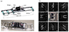 |
Figure 20 System configuration and multi-aspects SAR images. (a) The MV3DSAR system. (b) Optical image of the scene and multi-aspect SAR images. |
As is well known, datasets play a crucial role in the development for a certain field. The progress of SAR 3D imaging technology has long been constrained by insufficient datasets. This inadequacy manifests in two aspects. First, there is a shortage of multi-channel SAR data. Second, there is a lack of ground truth to assess the effectiveness and accuracy of various algorithms. Therefore, leveraging the accumulated data from the previous manned platform and utilizing the data acquired by the aforementioned UAV-borne system in regions such as Tianjin and Jiangsu, we have constructed the SAR Microwave Vision 3D Imaging dataset, known as the SARMV3D dataset. Dataset structure and an example of the dataset are summarized in Figure 21. This dataset addresses the scarcity of multi-channel SAR data and provides reference ground truth, enabling the evaluation of algorithmic performance and accuracy [38].
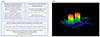 |
Figure 21 SAR MV 3D imaging dataset. (a) Structure and contents of the dataset. (b) Reference results by MV 3D imaging methods. |
The SARMV3D dataset comprises two auxiliary datasets for 3D electromagnetic scattering mechanism research and image visual semantics perception, along with a comprehensive dataset for SAR 3D imaging research based on microwave vision. Details of these three parts are as follows. The 3D electromagnetic scattering mechanism research dataset is used for studying and validating the correctness of electromagnetic modeling, characterization, and inversion estimation of 3D feature parameters for typical scattering mechanisms and their combinations. It mainly includes simulated, anechoic chamber measurements, and outdoor field measurement data for typical scattering mechanisms and their combinations. Another is the SAR image visual semantics perception dataset. It is designed for researching and validating the effectiveness and correctness of methods for extracting and identifying 3D primitives, structures, and targets from SAR images. This subset mainly comprises high-resolution SAR images and annotated results for typical buildings and structural prior information. Last but not least is the microwave vision-based SAR 3D imaging dataset. It is the primary comprehensive dataset that includes urban scenes, complex terrains, and typical targets. For each type, single-look complex images (SLC) obtained from TomoSAR or array InSAR system, corresponding imaging parameter files, 3D modeling data obtained from optical photography, and high-precision 3D point cloud data obtained from lidar, are all included.
The SARMV3D dataset has three versions, including Version 1.0, which was released in 2021 and is mainly based on data from the Aerospace Information Research Institute’s array InSAR system, as well as high-resolution SAR images from the Gaofen-3 satellite. Version 2.0 released in 2022 includes small UAV-based array InSAR data obtained in the Tianjin Lingang CBD using the MV3D SAR system, along with synchronized optical oblique photography and lidar point cloud. Version 3.0 released in 2024 includes data obtained at Suzhou aerospace information research institute using the full-polarization MV3D SAR system. Specifically, dataset of Yuncheng and Emei consists of SAR images from single aspect. Dataset of Tianjin consists of single polarization SLC images from eight aspects, while that of Suzhou consists of full polarization SLC images from eight aspects. These datasets have been made available on the website of Journal of Radars, attracting hundreds of research institutions and thousands of researchers globally to download and engage in related studies. This dataset contributes significantly to alleviating the scarcity of SAR 3D imaging datasets and promoting advancements in the field.
ANTICIPATED DEVELOPMENT TRENDS
As mentioned above, we have made significant progress in SAR microwave vision 3D imaging. However, being a novel theory, there are still numerous aspects awaiting exploration. To this end, building upon the existing research achievements, we have outlined the anticipated future directions in this domain. Consistent with the previous discussion, we categorize these directions into three aspects: theoretical framework, imaging algorithm design, and hardware systems with datasets.
Theoretical framework
Regarding theoretical framework, there are mainly two aspects. Firstly, it is imperative to further refine the concept of holographic SAR, exploring more detailed theoretical models to comprehensively and accurately characterize the microwave properties of targets. Secondly, cross-disciplinary collaboration must be addressed. Increased collaboration among radar signal processing, electromagnetics, computer vision, and related fields should be conducted to leverage expertise from diverse disciplines for more holistic advancements in SAR microwave vision 3D imaging.
SAR 3D imaging algorithm
As for 3D imaging algorithms, integration with advanced technologies is of top priority. Integration with emerging technologies such as deep learning to enhance capabilities in information extraction, feature recognition, and 3D reconstruction is promising. Besides, we should further investigate unsupervised and self-supervised learning methods to reduce reliance on extensively labeled data, enhancing the model’s generalization since SAR dataset is not as abundant as optical datasets. Generally, it is necessary to realize continuous refinement and advancement of algorithms and models for microwave vision-based SAR 3D imaging, focusing on improving accuracy, efficiency, and adaptability across diverse scenarios.
SAR systems and dataset
First, advancements in hardware systems should be emphasized, including the development of more sophisticated SAR systems, improved sensors, and enhanced data acquisition technologies to further improve imaging quality. Second, since the main purpose of SAR microwave vision 3D imaging is to realize high-quality low-cost reconstruction, real-time and onboard processing should be considered based on years of research. In the future, exploration and development of real-time and onboard processing capabilities should be conducted, enabling timely 3D imaging results for time-sensitive applications.
As for dataset construction, it is necessary to expand existing datasets and create benchmark datasets for comprehensive evaluation and benchmarking of different microwave vision-based SAR 3D imaging approaches. In order to promote holographic SAR research. we will construct more diverse imaging datasets containing multisource heterogeneous data, covering a wider range of scenes and targets to improve the theory’s robustness and generalization.
These anticipated developments collectively aim to propel microwave vision-based SAR 3D imaging into new frontiers, expanding its applications and advancing the state-of-the-art in the field.
CONCLUSION
SAR 3D imaging, compared to 2D imaging, provides richer and more diverse information, and becomes a recent research focus in the SAR imaging field. In response, SAR microwave vision 3D imaging, a new form that has emerged after two decades of 3D imaging development, integrates multiple disciplines, achieving high efficiency and low cost, and has the potential to further practicalize SAR 3D imaging. Traditional SAR 3D imaging relies solely on signal processing techniques, while SAR microwave vision 3D imaging introduces the concept of microwave vision, incorporating an intelligent theoretical framework for understanding microwave radar images. This results in an intelligent and efficient 3D imaging theory.
This paper provides a systematic review of SAR microwave vision 3D imaging. It starts by scientifically defining its conceptual framework and elaborating on core concepts. The theoretical framework of SAR microwave vision 3D imaging includes representation models, computational models, processing paradigms, and evaluation systems. Building on the concept of holographic SAR imaging, the paper proposes a representation model for microwave vision 3D imaging. It introduces an integrated model for intelligent processing and information extraction, evolving from traditional unidirectional processing models to new closed-loop feedback processing models. From the perspective of practical application promotion, a comprehensive evaluation system for 3D imaging performance is constructed.
The author’s team conducted extensive research on the above content, accumulating rich achievements over several years in imaging theory, algorithms, system development, and dataset construction. Notably, the constructed dataset is the most comprehensive in the field of SAR 3D imaging in China. The team’s theoretical algorithm research results were validated on this dataset, confirming the effectiveness of SAR microwave vision three-dimensional imaging methods. However, as an emerging development direction, SAR microwave vision 3D imaging still faces foundational and key technological challenges, requiring further breakthroughs in basic theory, imaging algorithms, and system development. The key is to integrate practical application needs, further improve, and promote the development of relevant technologies.
Data availability
The original data are available from corresponding authors upon reasonable request.
Funding
This work was supported by the National Natural Science Foundation of China (61991420, 61991421 and 61991424).
Author contributions
Conceptualization, X.Q. and C.D.; methodology, X.Q. and Z.J.; software, Q.Y., Z.J. and X.Q.; formal analysis, Q.Y., Z.J. and Z.Z.; investigation, X.Q. and Z.J.; resources, X.Q. and C.D.; data curation, X.Q., Z.J., Q.Y. and Z.Z.; writing—original draft preparation, X.Q. and Z.J.; writing—review and editing, X.Q. and Z.J.; visualization, Q.Y., Z.J. and Z.Z.; supervision, X.Q. and C.D.; project administration, X.Q. and C.D.; funding acquisition, X.Q. and C.D.
Conflict of interest
The authors declare no conflict of interest.
References
- Chibiao D, Xiaolan Q, Feng X, et al. Synthetic aperture radar three-dimensional imaging—From TomoSAR and array InSAR to microwave vision. J Radars 2019; 8: 693–709 [Google Scholar]
- La Prade G An analytical and experimental study of stereo for radar. Photogramm Eng 1963; 29: 294-300 [Google Scholar]
- Leberl F, Raggam J, Kobrick M. On stereo viewing of SAR images. IEEE Trans Geosci Remote Sens 1985; GE-23: 110-117. [Article] [NASA ADS] [CrossRef] [Google Scholar]
- Schmitt M, Zhu XX. Demonstration of single-pass millimeterwave SAR tomography for forest volumes. IEEE Geosci Remote Sens Lett 2015; 13: 202-206. [Article] [Google Scholar]
- Zhu XX, Bamler R. Tomographic SAR inversion by L1-norm regularization—The compressive sensing approach. IEEE Trans Geosci Remote Sens 2010; 48: 3839-3846. [Article] [NASA ADS] [CrossRef] [Google Scholar]
- Zhu XX, Bamler R. Very high resolution spaceborne SAR tomography in urban environment. IEEE Trans Geosci Remote Sens 2010; 48: 4296-4308. [Article] [NASA ADS] [CrossRef] [Google Scholar]
- Pasquali P, Prati C, Rocca F, et al. A 3-D SAR experiment with EMSL data. 1995 International Geoscience and Remote Sensing Symposium, IGARSS '95. Quantitative Remote Sensing for Science and Applications, Firenze: Italy, 1995; 1: 784–786 [CrossRef] [Google Scholar]
- Liang X, Wu Y, Ding C, et al. A novel 3-D reconstruction approach based on group sparsity of array InSAR. Sci Sin-Inf 2018; 48: 1051-1064. [Article] [CrossRef] [Google Scholar]
- Reigber A, Moreira A. First demonstration of airborne SAR tomography using multibaseline L-band data. IEEE Trans Geosci Remote Sens 2000; 38: 2142-2152. [Article] [NASA ADS] [CrossRef] [Google Scholar]
- Fornaro G, Lombardini F, Serafino F. Three-dimensional multipass SAR focusing: Experiments with long-term spaceborne data. IEEE Trans Geosci Remote Sens 2005; 43: 702-714. [Article] [NASA ADS] [CrossRef] [Google Scholar]
- Fornaro G, Lombardini F, Pauciullo A, et al. Tomographic processing of interferometric SAR data: Developments, applications, and future research perspectives. IEEE Signal Process Mag 2014; 31: 41-50. [CrossRef] [Google Scholar]
- Reale D, Fornaro G, Pauciullo A, et al. Tomographic imaging and monitoring of buildings with very high resolution SAR data. IEEE Geosci Remote Sens Lett 2011; 8: 661-665. [Article] [NASA ADS] [CrossRef] [Google Scholar]
- Caltagirone F. Status, results and perspectives of the Italian Earth Observation SAR COSMO-SkyMed. 2009 European Radar Conference (EuRAD), Rome: Italy, 2009; 330–334 [Google Scholar]
- Bi H, Jin S, Wang X, et al. High-resolution high-dimensional imaging of urban building based on GaoFen-3 SAR data. J Radars 2022; 11: 40–51 [Google Scholar]
- Giret R, Jeuland H, Enert P. A study of a 3D-SAR concept for a millimeter wave imaging radar onboard an UAV. First European Radar Conference (EuRAD), Amsterdam: Netherlands, 2004; 201–204 [Google Scholar]
- Nouvel J, Jeuland H, Bonin G, et al. A Ka band imaging radar: DRIVE on board ONERA motorglider. 2006 IEEE International Symposium on Geoscience and Remote Sensing, Denver: USA, 2006; 134–136 [CrossRef] [Google Scholar]
- Nouvel JF. ONERA DRIVE project. 2009 International Radar Conference "Surveillance for a Safer World" (RADAR 2009), Bordeaux: France, 2009; 1–4 [Google Scholar]
- Weiß M, Peters O, Ender J. First flight trials with ARTINO. 7th European Conference on Synthetic Aperture Radar, Friedrichshafen: Germany, 2008; 1–4 [Google Scholar]
- Klare J, Weiß M, Peters O, et al. ARTINO: A new high resolution 3D imaging radar system on an autonomous airborne platform. 2006 IEEE International Symposium on Geoscience and Remote Sensing, Denver: USA, 2006; 3842–3845 [CrossRef] [Google Scholar]
- Weiss M, Gilles M. Initial ARTINO radar experiments. 8th European Conference on Synthetic Aperture Radar, Aachen: Germany, 2010; 1–4 [Google Scholar]
- Zhang F, Liang X, Wu Y, et al. 3D surface reconstruction of layover areas in continuous terrain for multi-baseline SAR interferometry using a curve model. Int J Remote Sens 2015; 36: 2093-2112. [CrossRef] [Google Scholar]
- Jiao Z, Ding C, Qiu X, et al. Urban 3D imaging using airborne TomoSAR: Contextual information-based approach in the statistical way. ISPRS J Photogrammetry Remote Sens 2020; 170: 127-141. [Article] [NASA ADS] [CrossRef] [Google Scholar]
- Han D, Jiao Z, Zhou L, et al. Geometric constraints based 3D reconstruction method of tomographic SAR for buildings. Sci China Inf Sci 2023; 66: 112301. [Article] [CrossRef] [Google Scholar]
- Yan Q, Jiao Z, Qiu X, et al. Comparison between different TomoSAR imaging models for airborne platform flying at low altitude. Remote Sens 2022; 14: 5452. [Article] [CrossRef] [Google Scholar]
- Lin Y, Qiu X, Li H et al. Channel migration correction for low-altitude airborne SAR tomography based on keystone transform. IEEE Geosci Remote Sens Lett 2023; 20: 1-5 [Google Scholar]
- Du B, Qiu X, Zhang Z, et al. L1 minimization with perturbation for off-grid tomographic SAR imaging. J Radars 2022; 11: 62–70 [Google Scholar]
- Shi R, Zhang Z, Qiu X et al. A novel gradient descent least-squares (GDLSs) algorithm for efficient gridless line spectrum estimation with applications in tomographic SAR imaging. IEEE Trans Geosci Remote Sens 2023; 61: 1-13 [Google Scholar]
- Zhou G, Xu Z, Fan Y et al. HPHR-SAR-Net: Hyper-pixel high-resolution SAR imaging network based on nonlocal total variation . IEEE J Sel Top Appl Earth Obs Remote Sens 2023; 16: 8595-8608 [NASA ADS] [CrossRef] [Google Scholar]
- Chen J, Qiu X, Ding C, et al. CVCMFF net: Complex-valued convolutional and multifeature fusion network for building semantic segmentation of InSAR images. IEEE Trans Geosci Remote Sens 2022; 60: 5205714 [Google Scholar]
- Wang W, Xu H, Wei H, et al. Progressive building facade detection for regularizing array InSAR point clouds. J Radars 2022; 11: 144–156 [Google Scholar]
- Jiao Z, Qiu X, Dong S, et al. Preliminary exploration of geometrical regularized SAR tomography. ISPRS J Photogrammetry Remote Sens 2023; 201: 174-192. [Article] [NASA ADS] [CrossRef] [Google Scholar]
- Zhao Y, Xu J, Quan X, et al. Tomographic SAR imaging method based on sparse and low-rank structures. J Radars 2022; 11: 52–61 [Google Scholar]
- Li X, Zhang F, Li Y, et al. An elevation ambiguity resolution method based on segmentation and reorganization of TomoSAR point cloud in 3D mountain reconstruction. Remote Sens 2021; 13: 5118. [Article] [NASA ADS] [CrossRef] [Google Scholar]
- Wang S, Guo J, Zhang Y, et al. Multi-baseline SAR 3D reconstruction of vehicle from very sparse aspects: A generative adversarial network based approach. ISPRS J Photogrammetry Remote Sens 2023; 197: 36-55. [Article] [NASA ADS] [CrossRef] [Google Scholar]
- Li J, Xu Z, Li Z, et al. An unsupervised CNN-based multichannel interferometric phase denoising method applied to TomoSAR imaging. IEEE J Sel Top Appl Earth Observations Remote Sens 2023; 16: 3784-3796. [Article] [CrossRef] [Google Scholar]
- Wang M, Zhang Z, Qiu X et al. ATASI-Net: An efficient sparse reconstruction network for tomographic SAR imaging with adaptive threshold. IEEE Trans Geosci Remote Sens 2023; 61: 1-18 [Google Scholar]
- Qiu X, Jiao Z, Yang Z et al. Key technology and preliminary progress of microwave vision 3D SAR experimental system. J Radars 2022; 11: 1-19 [Google Scholar]
- Qiu X, Jiao Z, Peng L et al. SARMV3D-1.0: Synthetic aperture radar microwave vision 3D imaging dataset. J Radars 2021; 10: 485-498 [Google Scholar]
All Tables
All Figures
|
Figure 1 Schematic of SAR 3D imaging. |
| In the text | |
|
Figure 2 Semantic information extracted from SAR images. (a) Building instance segmentation. (b) Clustering results. (c) Building model reconstruction. |
| In the text | |
|
Figure 3 The 3D scattering mechanism from SAR images. |
| In the text | |
|
Figure 4 Paradigm of processing. |
| In the text | |
|
Figure 5 Diagrammatic sketch of microwave vision SAR 3D imaging. |
| In the text | |
|
Figure 6 Spherical SAR 3D imaging model and comparison between different models. (a) Planar wavefront model. (b) Spherical wavefront model. (c) Reconstruction results by different models. |
| In the text | |
|
Figure 7 Models and results. (a) Flowchart of channel-migration correction. (b) Results before and after CM. |
| In the text | |
|
Figure 8 Off-grid TomoSAR imaging method. (a) Magnitude estimation performance. (b) Elevation estimation performance. |
| In the text | |
|
Figure 9 Side view of reconstruction result in radar geometry by traditional method and GDLS. (a) Traditional method. (b) Proposed GDLS method. |
| In the text | |
|
Figure 10 Performance comparison of IVDST-ANM and other state-of-art technology, and reconstruction result of urban areas. (a) RMSE versus SNR by different method. (b) Reconstructed point cloud by IVDST-ANM. |
| In the text | |
|
Figure 11 Network structure and segmentation result of CVCMFF Net. |
| In the text | |
|
Figure 12 Intermediate results of line and plane detection results. |
| In the text | |
|
Figure 13 Geometric constraint SAR 3D imaging. (a) Geometrical structures from SAR images. (b) Co-registered SAR and lidar point cloud. |
| In the text | |
|
Figure 14 Geometric constraint SAR 3D imaging based on statistical model. (a) Large-scale case. (b) Small-scale case. |
| In the text | |
|
Figure 15 Reconstructed point cloud of mountainous areas based on proposed method. |
| In the text | |
|
Figure 16 Pol-array-InSAR processing model and results. |
| In the text | |
|
Figure 17 Network structure and 3D imaging results by different methods. (a) Network structure of SACNet. (b) Point cloud completion results. |
| In the text | |
|
Figure 18 Diagrammatic sketch of proposed denoising CNN. |
| In the text | |
|
Figure 19 Details and performance of ATASI-Net. (a) Overall architecture of ATASI-Net and the data flow of each module. (b) Point cloud comparison results based on the traditional CS algorithm and the proposed ATASI-Net model. (c) Segmentation results after threshold visualization. |
| In the text | |
|
Figure 20 System configuration and multi-aspects SAR images. (a) The MV3DSAR system. (b) Optical image of the scene and multi-aspect SAR images. |
| In the text | |
|
Figure 21 SAR MV 3D imaging dataset. (a) Structure and contents of the dataset. (b) Reference results by MV 3D imaging methods. |
| In the text | |
Current usage metrics show cumulative count of Article Views (full-text article views including HTML views, PDF and ePub downloads, according to the available data) and Abstracts Views on Vision4Press platform.
Data correspond to usage on the plateform after 2015. The current usage metrics is available 48-96 hours after online publication and is updated daily on week days.
Initial download of the metrics may take a while.