| Issue |
Natl Sci Open
Volume 3, Number 5, 2024
Special Topic: Microwave Vision and SAR 3D Imaging
|
|
|---|---|---|
| Article Number | 20230085 | |
| Number of page(s) | 17 | |
| Section | Information Sciences | |
| DOI | https://doi.org/10.1360/nso/20230085 | |
| Published online | 20 August 2024 | |
RESEARCH ARTICLE
RM-CSTV: An effective high-resolution method of non-line-of-sight millimeter-wave radar 3-D imaging
School of Information and Communication Engineering, University of Electronic Science and Technology of China, Chengdu 611731, China
* Corresponding author (email: weishunjun@uestc.edu.cn)
Received:
15
December
2023
Revised:
26
January
2024
Accepted:
28
May
2024
Non-line-of-sight (NLOS) imaging is a novel radar sensing technology that enables the reconstruction of hidden targets. However, it may suffer from synthetic aperture length reduction caused by ambient occlusion. In this study, a complex total variation (CTV) regularization-based sparse reconstruction method for NLOS three-dimensional (3-D) imaging by millimeter-wave (mmW) radar, named RM-CSTV method, is proposed to improve imaging quality and speed. In this scheme, the NLOS imaging model is first introduced, and associated geometric constraints for NLOS objects are established. Second, an effective high-resolution NLOS imaging method based on the range migration (RM) kernel and complex sparse joint total variation constraint, dubbed as modified RM-CSTV, is proposed for 3-D high-resolution imaging with edge information. The experiments with multi-type NLOS targets show that the proposed RM-CSTV method can provide effective and high-resolution NLOS targets 3-D imaging.
Key words: NLOS imaging / 3-D-SAR / 3-D imaging / sparse reconstruction
© The Author(s) 2024. Published by Science Press and EDP Sciences.
 This is an Open Access article distributed under the terms of the Creative Commons Attribution License (https://creativecommons.org/licenses/by/4.0), which permits unrestricted use, distribution, and reproduction in any medium, provided the original work is properly cited.
INTRODUCTION
Non-line-of-sight (NLOS) imaging is a novel method used to reconstruct hidden targets located behind corners. The NLOS imaging technique leverages the characteristics of multipath electromagnetic (EM) propagation. As EM and light waves bounce off the surface of the line-of-sight (LOS) medium, they illuminate the hidden target and reflect back to the detector. Through the process, valuable information such as the range, azimuth, and geometry of the NLOS target can be detected from the multipath echo. With the capacity of all-day and all-weather working, the NLOS radar imaging has received widespread attention. Combined with the three-dimensional (3-D) synthetic aperture radar (SAR) imaging algorithm, it becomes possible to reconstruct and identify high-precision stereo images of hidden targets located behind obstacles.
The NLOS imaging technology originated from the study of optical methods. In recent years, there have been many studies on NLOS scene imaging in the optical field [1-5]. In ref. [6], based on the time-of-flight (TOF) theory, the scholars utilize a femtosecond laser and an ultrafast photodetector array to reconstruct the 3-D images of the hidden objects. In ref. [7], Rapp et al. exploited an arc scanning light source to control the illuminated portion of the hidden area and achieved 2.5 dimensional veiled scene reconstruction. For the extraction of hidden target details, Liu et al. [8] proposed an NLOS imaging algorithm based on a Bayesian framework to achieve the recovery of fine details. However, the optical NLOS sensing requires expensive optical equipment and is heavily affected by meteorology. Other NLOS imaging technologies, such as acoustic [9] and WiFi [10, 11], also have similar limitations. Compared to optical devices, radar is inexpensive and stable. Meanwhile, there are several 3-D imaging achievements in the radar field. Hence, NLOS radar imaging has great potential.
T-shaped hidden scene is a research hotspot of existing radar NLOS sensing. The target and the radar are blocked by the obstacle, and the EM waves cannot illuminate the target in the LOS direction[12-19]. In ref. [20], Li et al. achieved multi-hidden target localization by measuring and eliminating the ghosts caused by multipath. For LOS 3-D radar imaging[21-27], Wang et al. [28] proposed a perceptual learning framework by unfolding the fast iterative shrinkage-thresholding algorithm (FISTA) and exploring the sparse prior. For LOS 3-D microwave vision[29-31], several SAR 3-D imaging systems and methods are discussed. In refs. [32, 33], the scholars focus on tomographic synthetic aperture radar (TomoSAR) and proposed a method dubbed ATASI-Net, which overcomes the drawbacks of the traditional algorithm, such as weak noise resistance and high computational complexity.
For radar NLOS sensing, the main research direction is to focus on 3-D positioning[19, 20, 34-36]. In order to realize NLOS 3-D imaging, we have carried out a series of studies[37-41]. We proposed the MSBP algorithm for the looking around corner (LAC) case and verified the method by the experiment data collected by MIMO millimeter wave array antennas[42]. Although high-resolution 3-D reconstruction of hidden targets was achieved, the signal undersampling problem caused by complex NLOS scenes exists, which leads to the failure of proposed algorithm. Thus, a no prior information required joint compressed sensing algorithm with total variation (TV) regularization, L1 norm and range migration (RM) kernel called RM-CSTV is proposed to achieve 3-D high-resolution imaging.
In this study, for the echo model of NLOS imaging is different from that of LOS region due to the multipath effect in electromagnetic propagation, the matrix model and wave-number domain model of NLOS echo are first analyzed theoretically, and the detection and correction methods without prior information without prior information of NLOS targets are given according to NLOS geometric constraints. Additionally, aiming at the sparse characteristics of NLOS echoes, we propose a 3-D sparse reconstruction method of NLOS based on L1 norm and complex TV regular, and an effective 3-D imaging method based on RM kernel function is proposed to solve the problem of huge computation. Furthermore, we build up NLOS 3-D imaging experimental system to verify the effectiveness of the proposed method. Finally, we summarize the content of this study.
The main contribution of this article are as follow: (1) a geometric constraint based NLOS target detecting method for array SAR 3-D imaging is proposed, which provides a theoretical basis for 3-D NLOS target detection; (2) compared with present algorithm and our previous[42], CSTV method avoids the loss of contour information, and exploits the sparse characteristic of NLOS echo to achieve high resolution imaging; (3) by introducing the RM kernel, the calculation time of RM-CSTV method reduced two orders of magnitude compared with CSTV method, which provides a possibility for practical application of NLOS 3-D imaging. The rest of this study is organized as follows. Section 2 introduces the problem formulation related to NLOS 3-D imaging is analyzed. In section 3, the theories and algorithms flows of NLOS targets 3-D effective reconstruction is proposed. The experimental scene and 3-D imaging results are shown and discussed in section 4. Finally, we give a conclusion in section 5.
PROBLEM FORMULATION
In this section, we present the basic theory for mmW NLOS 3-D imaging in the “T" type LAC scene. First, the geometric constraints of LAC scene is discussed for detecting the reflecting walls. Then, to obtain high-resolution imaging, the CS theory based model of NLOS radar echo is proposed. Finally, the theoretical resolution for mmW NLOS imaging system is analyzed.
A typical NLOS scene is shown in Figure 1. The millimeter wave undergoes reflection by the reflecting surface to illuminate the NLOS target, and is subsequently received by the array after undergoing three scatterings. The Considering distance of representation in linear array scanning mmW radar NLOS 3-D imaging, the single trip of signal R can be described as (1)
(1)
 |
Figure 1 The layout of a typical LAC scene. The wall is used as an intermediary mmW propagating, and the echoes are received from the three-bounces path. |
Specifically, the scattering process can be seen as ideally-reflection when the reflecting surface roughness height Δh satisfied (2)where λ is signal wave length, θin is the angle of incidence. In this scenario, deterministic reflection path exhibit, the transmitting and reflecting distances of given array element for the designated target are equivalent.
Through the three-bounce path, the single point NLOS target echo can be described as (3)where
  , f0 denotes carrier frequency, σ is the scattering coefficient of target,
  denotes bidirectional reflection distribution function (BRDF), influenced by angle of incidence θi and angle of emergence θo. K is frequency slope.
Expanding to 3-D targets imaging, the echo can be described by exploiting the CS method: (4)where
  is signal echo vector,
  is the measure matrix.
  is the scattering coefficient of virtual NLOS targets, n is the noise.
Additionally, expressing eq. (3) in wavenumber domain for reducing the computational complexity, we can obtain the scattering coefficient x(Ps, r) of range plane r as follows: (5)where IFT2D(·) is the two-dimensional inverse Fourier transform operator, Ps is the position of scattering coefficient, Pa is the antenna phase center,
  , and ky can be denoted as
 (6)
(6)
In this study, we exploit geometrical relationships in the NLOS scene to reconstruct the hidden target in a real position. As shown in eq. (4), the NLOS targets are reconstructed in a virtual position with normal LOS objects.
Assuming that the reflective surface is similar to vertical and flat, which can be seen as the mirror reflector for mmW radar wave. Based on the 2D image, the position of the reflective wall can be determined. Considering the x-y axis in z=z0 slice, the reflective surface is described as Ax+By+C=0.
Hence, the relationship between position of virtual target  and real target PT is satisfied:
 (7)
(7)
The equal-height slice of NLOS scene is shown in Figure 2. The target T is located at  , and the reflecting wall W1 is the intermediary for multi-path echo. The radar antenna array A is located between the points A1 and A2. As shown in Figure 2, for the impact of W2 , which might be buildings or cars in the urban environment, the direct path between antenna and target is blocked. The imaging space that can provide a direct echo for radar is called LOS region Ωlos. And the hidden space caused by obstacles is called NLOS region Ωnlos. The mainly propagation of NLOS echo is constituted by three parts of bounces:
  [42], where A is on the line segment
  .
.
 |
Figure 2 The Geometric relationship between radar array, reflecting wall and NLOS target. |
For the relationship shown in Figure 2, the virtual NLOS targets can be detected by the following constraints: (8)where A1 and A2 are the two endpoint coordinate vectors of the antenna array, and W11 is the point on the reflecting wall W1. The incident point of the echo corresponding to the end of the radar array on the reflecting wall are PWT1 and PWT2, which can be calculated by
 (9)
(9) (10)
(10)
METHODOLOGY
In this section, the CS theory based NLOS 3-D imaging method is proposed. The 3-D reconstruction is divided into three steps: high-resolution imaging, reflecting surface judgment, and virtual targets adjusting. Meanwhile, the CS algorithms working in time-domain with high dimension matrix-ector operators employed in the optimization iterations generate large-scale storage of the measurement matrix and huge computational complexity. We proposed a novel RMA kernel-based STV 3-D imaging method to overcome these shortcoming. In this section, the sparse and total variation regularization operator combined (STV) high-resolution 3-D targets reconstructing method is introduced firstly. And then by exploiting the geometric constraints, we correct the virtual target to real position without any previous knowledge. At last, the RMA kernel is embedded into STV to improve the calculation speed.
The sparse-TV algorithm
Considering the CS theory, the echo in eq. (11) can be transfered into the following function: (11)where
  is NLOS echo vector,
  is the measure matrix proposed in ref. [43].
  is the scattering coefficient of virtual NLOS targets, n is the noise.
Generally, to obtain high-resolution imaging, eq. (11) is solved by the following optimization method: (12)where
  is used to characterize sparsity,
  denotes the 2D TV norm, which is using for preserving the contour information.
  and
and  are the parameters for balancing the influence of these regular terms. Considering that the NLOS targets are isotropy, CTV operator can be described as
 (13)with
 (14)where
  is the unit matrix.
Hence, the estimation of scattering coefficient  can be transformed into the following unconstrained optimization problem:
 (15)
(15)
Convert eq. (15) to the following two variable representations: (16)
(16)
By introducing Lagrangian multiplier  , the argument Lagrangian function can be described as
 (17)
(17)
Hence, the scattering coefficient x in eq. (17) can be solved by the following three steps[44].
Step 1: Minimized the scattering coefficient x: (18)which can be solved by finding the gradient,
 (19)
(19)
Step 2: The problem of optimizing z1 and z2 can be solved by divide it into the following two sub-problems, (20)
(20) (21)
(21)
The sub-problems can be solved by exploiting the iterative shrinkage threshold (ISTA), (22)
(22) (23)where
  is the iterative shrinkage threshold function[45].
Step 3: Solving the Lagrange multipliers u (24)
(24)
Sparse-TV algorithm
RMA kernel based effective sparse-TV imaging
For solving the shortcoming that CS based algorithms relies heavily computing resource, the RMA kernel is proposed to replace the measurement matrix Ψ. The RM kernel solve the iteration problem in the Fourier domain by exploiting the 2D fast Fourier transformation.
Consequently, we pad and transform the NLOS echo  from
from  by the function
  to perform the 2D Fourier transform of the corresponding size. And we suppose that
  is the matrix representing virtual imaging.
For the echo expressed in eq. (5), eq. (4) and its inverse operation can be written with RM kernel function as follow: (25)
(25) (26)where
  denotes the Hadamard product, RM(·) and RM†(·) are RM kernel and its inverse operation. Notably, eq. (25) is a classical near-field imaging assumption, and it suffers from decline when facing the downsampling performed.
The phase propagation matrix and its inverse which shown in eqs. (25) and (26) are defined as (27)where
  is described as the frequency wavenumber variable matrix.
We introduce the RM kernel and its inverse operation into the optimization problem described in eq. (15). The problem can be transformed into (28)
(28)
Since the RM kernel and its inverse kernel satisfy (29)the RM kernel based sparse-TV algorithm optimization is concluded as
 (30)
(30)
RM-CSTV Algorithm
NLOS region extraction and correction
In order to avoid the dependence on the prior information, a fast imaging of the x-y plane is first performed to perceive the horizontal wall shaped object in the NLOS scene. By Hough transform and NLOS geometric constraint which given in eq. (8), reflective surfaces in 2D slices are detected. Then, the NLOS imaging region is separated and corrected by eq. (7).
EXPERIMENTS AND RESULTS
In this section, the performance of proposed imaging method on NLOS 3-D sparse reconstruction is validated by NLOS high-resolution imaging experiment system, and the comparison of NLOS imaging by RM-CSTV, MSBP and mirror-symmetry based traditional compressed sensing (MSCS) method has been given, qualitative results are given with different sampling rates.
Considering the complexity of electromagnetic propagation in NLOS systems, it is difficult to simulate NLOS echoes accurately in a simulated system. Therefore, we use measured data to validate the imaging system and imaging algorithms.
To verify the imaging principle and algorithm performance of NLOS radar three-dimensional imaging. The imaging system consists of three parts: the data processing module, the radio frequency (RF) module, and the high-precision antenna motion rail module. The NLOS 3-D SAR imaging experimental system mainly uses the “TI AWR2243" millimeter-wave radar sensor and the “DCA1000" data acquisition card as the RF module, operating in a 1T1R single-input single-output (SISO) mode. The equivalent 2D virtual array is achieved using the antenna motion module.
For the antenna motion module, the synthesized array element has a length of 400 mm in both the x-axis and z-axis, i.e., Dx=Dz=400 mm. To satisfy the condition of array without grating lobes, Array element spacing in the x-axis is set to dx=1 mm, and Array element spacing in the z-axis is set to dz=2 mm. The original data dimension size is 200×400×256.
To validate the accuracy of the RM-CSTV algorithm for target localization and the quality of 3-D imaging, two sets of near-field NLOS imaging experiments were conducted using two metal tools and a metal flower stand as non-line-of-sight targets. Additionally, to achieve the experimental scene under ideal conditions, four pieces of the same mmW absorbing material were used to absorb possible clutter, and aluminum foil was pasted on the reflecting surface to achieve ideal reflection of electromagnetic waves on the reflecting surface.
To evaluate the performance of the proposed algorithm, this chapter mainly uses image entropy (ENT), image contrast (IC), image sharpness (SHA), and computation time for algorithm evaluation.
Image entropy is a statistical measure that reflects the average amount of information in an image. For the same imaging scene, a lower image entropy indicates a better focus effect and higher image quality, without causing any loss of image information. Image entropy can be defined as follows: (31)where IS(i, j, k) represents the complex value corresponding to the (i, j, k)th pixel in the 3-D imaging result.
Image contrast is an estimation of the distinguishable brightness levels, and higher contrast indicates better image quality. It can be represented as follows: (32)where I, J, K denote the lengthes of 3-D result.
Image sharpness (SHA) is an indicator that reflects the clarity of the image plane and the sharpness of the image edges. The higher the image sharpness, the better the quality of test image. (33)
(33)
The NLOS virtual target correction
As shown in Figure 3, the virtual antenna array is represented by the blue lines, which indicate the length and position of the array in the horizontal dimension. The gap width between the occluding surface and the reflecting wall is denoted by dw=300 mm, and the angle between the scanning array and the wall is denoted by θs=50°. The dimensions of the metal knives are shown in Figure 3B. The length and width of the kitchen knife are L1=290 mm and W1=60 mm, and the length and width of the small knife are L2=226 mm and W2=23 mm. The two knives are inserted into square foam blocks with side lengths of L3=200 mm and L4=150 mm.
 |
Figure 3 NLOS 3-D imaging experiment scene. (A) Metal knives experiment scenario; (B) optical images of metal knives. |
Figure 4 represents the range-compressed echoes of the metal tools in the distance domain. The range echoes from the reflecting wall mainly concentrate around the 200th distance cell, while the echoes from the occluding surface are weaker due to the presence of absorbing material, and the targets echo is focused around the 100th distance cell. Around the 250th distance cell, clear pulse compression results provided by the two virtual knives can be observed, with the echo from target T2 being significantly stronger than the target T1 with a smaller reflecting cross section (RCS).
 |
Figure 4 Echo data of knives. (A) Range-pulse compression result; (B) two-dimensional imaging results of the original NLOS echo; (C) three-dimensional imaging results of the original NLOS echo. |
Significantly, the detection of NLOS target exists reflecting error. By exploiting mirror correction denoted at eq. (7), the maximum projection along the xz plane of NLOS 3-D result is shown in Figure 5. The sampling rate of the NLOS echo is 70%. BP, MSCS and RM-CSTV methods are exploited for 3-D reconstruction. As show in Figure 5C, the edge information is retained, and the reflecting error is corrected.
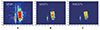 |
Figure 5 2D maximum projection results of NLOS 3-D imaging. (A) MSBP method; (B) MSCS method; (C) RM-CSTV method. |
The 3-D imaging result
To verify the robustness of proposed method, ornaments are 3-D reconstructed as another NLOS targets. The experiment scene is built as shown in Figure 6. And the size of the ornaments are shown in Figure 6B.
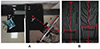 |
Figure 6 NLOS 3-D imaging experiment scene. (A) Metal knives experiment scenario; (B) optical images of metal knives. |
For the NLOS experiments, we compare the performance of MSBP, RMA, CSTV, and RM-CSTV (Figures 7 and 8). As reported in Tables 1 and 2, CSTV method has the longest operation time because of relying on large-scale matrix operations and multiple iterations, which is far from meeting the real-time requirements in radar imaging, but it has high image contrast at each sampling rate. The RMA method has the lowest operation time, but its imaging quality is poor, and its imaging results deteriorate sharply as the sampling rate decreases. The various imaging metrics of the MSBP method are between the RMA method and the compressed sensing method.
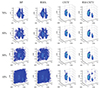 |
Figure 7 NLOS knives targets 3-D imaging result. |
 |
Figure 8 NLOS ornament targets 3-D imaging result. |
Quantitative comparisons and speed evaluations of knives targets
Quantitative comparisons and speed evaluations of ornament targets
Even in full sampling conditions, the BP and RMA imaging results are significantly affected by side lobes and clutter interference, with the edges of the objects being heavily polluted by noise. In contrast, the proposed algorithm effectively suppresses image side lobes and filters out a large amount of background clutter, resulting in clearer images and significantly improving imaging quality. Furthermore, the proposed algorithm successfully recovers partial detailed contours of the target even at low sampling rates, further proving the effectiveness and high performance of the algorithm.
Compared with the other three methods, the RM-CSTV method can achieve lower image entropy and higher image sharpness at the sampling rates of 70%, 50%, and 30%, which indicates that the proposed method has better image focusing effect. At the same time, the imaging time required by the proposed method is reduced by at least two orders of magnitude.
CONCLUSION AND DISCUSSION
In this article, we proposed an accelerated mmW NLOS 3-D sparse reconstruction method, i.e., RM-CSTV. The algorithm has the capability of not only reconstructing the NLOS targets with high resolution from multipath echoes in the LAC situation but also preserving the edge information. Using only a single radar array and single imaging, reflective surfaces are extracted from the LOS and NLOS mixed echoes and used to correct the position of the NLOS target. Considering the TV and sparse constraints of the target, the high-resolution problem of NLOS radar imaging is transformed into the optimization problem with multiconstraint. By solving the multiconstraint problem, defocuses of NLOS images are suppressed, and the contour information is preserved. Also, an RM kernel based accelerated algorithm is proposed to improve computational efficiency. With the RM-CSTV method, a well-focus and edge sharpness 3-D image can be obtained by the ADMM method to solve the optimization problem with sparse and TV constraints. Extensive NLOS 3-D mmW imaging experiments, including multitarget with 3-D characteristics, the weakly sparse surface target and weapons, validate the superiority of the RM-CSTV algorithm over the existing NLOS imaging methods in terms of both quality and efficiency. Except visually verifying that the NLOS imaging results of the proposed method have a precise contour, the indexes of ENT, Contrast, SHA and TBR are used to quantitatively ascertain the performance of our approach. Meanwhile, the acceleration method introduced RM kernel is two orders of magnitude times faster than the original method.
Funding
This work was supported by the National Natural Science Foundation of China (62271108).
Author contributions
X.L. and S.W. designed the research and analyzed the data. S.W. supervised the project. W.P., L.K. and X.Z. conducted the system demonstration and the experimental scheme designing. X.L. and X.C. collected the NLOS 3-D radar data. Y.W. and X.C preprocessed the data. Y.W. and S.G. analyzed the results. X.L. and S.W. co-wrote the manuscript. All authors contributed to the discussions.
Conflict of interest
The authors declare no conflict of interest.
References
- Wu C, Liu J, Huang X, et al. Non-line-of-sight imaging over 1.43 km. Proc Natl Acad Sci USA 2021; 118: e2024468118. [Article] [CrossRef] [PubMed] [Google Scholar]
- Faccio D, Velten A, Wetzstein G. Non-line-of-sight imaging. Nat Rev Phys 2020; 2: 318-327. [Article] [NASA ADS] [CrossRef] [Google Scholar]
- Nam JH, Brandt E, Bauer S, et al. Low-latency time-of-flight non-line-of-sight imaging at 5 frames per second. Nat Commun 2021; 12: 6526. [Article] [NASA ADS] [CrossRef] [PubMed] [Google Scholar]
- Wang Y, Zhang Y, Huang M, et al. Accurate but fragile passive non-line-of-sight recognition. Commun Phys 2021; 4: 88. [Article] [NASA ADS] [CrossRef] [Google Scholar]
- Willomitzer F, Rangarajan PV, Li F, et al. Fast non-line-of-sight imaging with high-resolution and wide field of view using synthetic wavelength holography. Nat Commun 2021; 12: 6647. [Article] [CrossRef] [PubMed] [Google Scholar]
- Kirmani A, Hutchison T, Davis J, et al. Looking around the corner using transient imaging. In: Proceedings of the 2009 IEEE 12th International Conference on Computer Vision. Kyoto: IEEE, 2009, 159-166. [Google Scholar]
- Rapp J, Saunders C, Tachella J, et al. Seeing around corners with edge-resolved transient imaging. Nat Commun 2020; 11: 5929. [Article] [NASA ADS] [CrossRef] [PubMed] [Google Scholar]
- Liu X, Wang J, Xiao L, et al. Non-line-of-sight imaging with arbitrary illumination and detection pattern. Nat Commun 2023; 14: 3230. [Article] [NASA ADS] [CrossRef] [PubMed] [Google Scholar]
- Lindell DB, Wetzstein G, Koltun V. Acoustic non-line-of-sight imaging. In: Proceedings of the IEEE/CVF Conference on Computer Vision and Pattern Recognition. Long Beach: IEEE, 2019, 6780-6789. [Google Scholar]
- Adib F, Katabi D. See through walls with WiFi! In: Proceedings of the ACM SIGCOMM 2013 Conference on SIGCOMM. Hong Kong, 2013, 75-86. [CrossRef] [Google Scholar]
- Chen S, Yang W, Xu Y, et al. AFall: Wi-Fi-based device-free fall detection system using spatial angle of arrival. IEEE Trans Mobile Comput 2023; 22: 4471-4484. [Article] [CrossRef] [Google Scholar]
- Xiang Y, Guo S, Xia S, et al. NLOS target positioning method based on UAV millimeter-wave radar. IEEE Sens J 2024; 24: 1975-1987. [Article] [CrossRef] [MathSciNet] [Google Scholar]
- Tang L, Guo S, Jian Q, et al. Through-wall human activity recognition with complex-valued range-time-doppler feature and region-vectorization convGRU. IEEE Trans Geosci Remote Sens 2023; 61: 5111014. [Article] [Google Scholar]
- Zhu Z, Guo S, Chen J, et al. Non-line-of-sight targets localization algorithm via joint estimation of DoD and DoA. IEEE Trans Instrum Meas 2023; 72: 8506311. [Article] [Google Scholar]
- Xue S, Guo S, Wu P, et al. NLOS target localization method in long L-shaped scenario with SISO UWB radar. In: Proceedings of 2023 3rd International Conference on Frontiers of Electronics, Information and Computation Technologies (ICFEICT). Yangzhou: IEEE, 2023, 525-530. [CrossRef] [Google Scholar]
- Liu X, Chen J, Guo S, et al. Non-line-of-sight human vital sign detection method based on multipath signals fusion. In: Proceedings of the 2023 3rd International Conference on Frontiers of Electronics, Information and Computation Technologies (ICFEICT). Yangzhou: IEEE, 2023, 489-496. [CrossRef] [Google Scholar]
- Shen Y, Zhang M, Wu Y, et al. Darting-out target detection with nlos signals for vehicle mimo mmwave radar. In: Proceedings of 2023 IEEE Radar Conference (RadarConf23). San Antonio: IEEE, 2023, 1-6. [Google Scholar]
- Wu P, Chen J, Guo S, et al. NLOS positioning for building layout and target based on association and hypothesis method. IEEE Trans Geosci Remote Sens 2023; 61: 5101913. [Article] [Google Scholar]
- Chen J, Guo S, Luo H, et al. Non-line-of-sight multi-target localization algorithm for driver-assistance radar system. IEEE Trans Veh Technol 2023; 72: 5332-5337. [Article] [CrossRef] [Google Scholar]
- Li S, Guo S, Chen J, et al. Multiple targets localization behind L-shaped corner via UWB radar. IEEE Trans Veh Technol 2021; 70: 3087-3100. [Article] [CrossRef] [Google Scholar]
- Shen R, Wei S, Zhou Z, et al. High resolution SAR tomography 3-D imaging via sparse recovery deep learning network. In: Proceedings of 2022 3rd China International SAR Symposium (CISS). Shanghai: IEEE, 2022, 1-5. [Google Scholar]
- Wang M, Wei S, Zhou Z, et al. 3-D SAR autofocusing with learned sparsity. IEEE Trans Geosci Remote Sens 2022; 60: 5235818. [Article] [Google Scholar]
- Zhou Z, Wei S, Zhang H, et al. SAF-3-DNet: Unsupervised AMP-inspired network for 3-D MMW SAR imaging and autofocusing. IEEE Trans Geosci Remote Sens 2022; 60: 5234915. [Article] [Google Scholar]
- Wei S, Zhou Z, Wang M, et al. Learning-based split unfolding framework for 3-D mmW radar sparse imaging. IEEE Trans Geosci Remote Sens 2022; 60: 5229317. [Article] [Google Scholar]
- Wang M, Wei S, Zhou Z, et al. 3-D SAR data-driven imaging via learned low-rank and sparse priors. IEEE Trans Geosci Remote Sens 2022; 60: 5228117. [Article] [Google Scholar]
- Lin Y, Qiu X, Li H, et al. Channel migration correction for low-altitude airborne SAR tomography based on keystone transform. IEEE Geosci Remote Sens Lett 2023; 20: 4011805. [Article] [Google Scholar]
- Lv X, Qiu X, Yu W, et al. Simulation-aided SAR target classification via dual-branch reconstruction and subdomain alignment. IEEE Trans Geosci Remote Sens 2023; 61: 5214414. [Article] [Google Scholar]
- Wang M, Wei S, Shi J, et al. 3-D SAR imaging via perceptual learning framework with adaptive sparse prior. IEEE Trans Geosci Remote Sens 2023; 61: 5202716. [Article] [Google Scholar]
- Ding C, Qiu X, Xu F, et al. Synthetic aperture radar three-dimensional imaging—From tomosar and array insar to microwave vision. J Radars 2019; 8: 693-709. [Google Scholar]
- Qiu X, Jiao Z, Peng L, et al. SARMV3D-1.0: Synthetic aperture radar microwave vision 3D imaging dataset. J Radars 2021; 10: 485-498. [Google Scholar]
- Qiu X, Jiao Z, Yang Z, et al. Key technology and preliminary progress of microwave vision 3D SAR experimental system. J Radars 2022; 11: 1-19. [Google Scholar]
- Du B, Qiu X, Zhang Z, et al. L1 minimization with perturbation for off-grid tomographic SAR imaging. J Radars 2022; 11: 62-70. [Google Scholar]
- Wang M, Zhang Z, Qiu X, et al. ATASI-Net: An efficient sparse reconstruction network for tomographic SAR imaging with adaptive threshold. IEEE Trans Geosci Remote Sens 2023; 61: 4701918. [Article] [Google Scholar]
- Yang X, Fan S, Guo S, et al. NLOS target localization behind an L-shaped corner with an L-band UWB radar. IEEE Access 2020; 8: 31270-31286. [Article] [NASA ADS] [CrossRef] [Google Scholar]
- Guo S, Zhao Q, Cui G, et al. Behind corner targets location using small aperture millimeter wave radar in NLOS urban environment. IEEE J Sel Top Appl Earth Observations Remote Sens 2020; 13: 460-470. [Article] [CrossRef] [Google Scholar]
- Chen J, Zhang Y, Guo S, et al. Joint estimation of NLOS building layout and targets via sparsity-driven approach. IEEE Trans Geosci Remote Sens 2022; 60: 5114513. [Article] [Google Scholar]
- Wen Y, Wei S, Liu X, et al. Non-line-of-sight isar imaging via millimeter-wave automotive radar. In: Proceedings of the IGARSS 2023 - 2023 IEEE International Geoscience and Remote Sensing Symposium. Pasadena: IEEE, 2023, 1229-1232. [CrossRef] [Google Scholar]
- Liu X, Wei S, Wei J, et al. Non-line-of-sight millimeter-wave radar 3-D sparse reconstruct via msstv method. In: Proceedings of 2022 IEEE 9th International Symposium on Microwave, Antenna, Propagation and EMC Technologies for Wireless Communications (MAPE). Chengdu: IEEE, 2022, 424-427. [CrossRef] [Google Scholar]
- Wen Y, Wei S, Wei J, et al. Non-line-of-sight imaging of hidden moving target using millimeter-wave inverse synthetic aperture radar. In: Proceedings of the IGARSS 2022 - 2022 IEEE International Geoscience and Remote Sensing Symposium. Kuala Lumpur: IEEE, 2022, 555-558. [CrossRef] [Google Scholar]
- Wei J, Wei S, Zeng X, et al. Non-line-of-sight SAR imaging by multi-scattering of millimeter-wave. In: Proceedings of the 2021 CIE International Conference on Radar (Radar). Haikou: IEEE, 2021, 259-263. [CrossRef] [Google Scholar]
- Cai X, Wei S, Liu X, et al. Compressed sensing imaging of mmw automotive radar via non-line-of-sight observation. In: Proceedings of IGARSS 2023 - 2023 IEEE International Geoscience and Remote Sensing Symposium. Pasadena: IEEE, 2023, 1225-1228. [CrossRef] [Google Scholar]
- Wei S, Wei J, Liu X, et al. Nonline-of-sight 3-D imaging using millimeter-wave radar. IEEE Trans Geosci Remote Sens 2022; 60: 5106518. [Article] [Google Scholar]
- Wei SJ, Zhang XL, Shi J. Compressed sensing linear array SAR 3-D imaging via sparse locations prediction. In: Proceedings of 2014 IEEE Geoscience and Remote Sensing Symposium. Quebec City: IEEE, 2014, 1887-1890. [Google Scholar]
- Boyd S, Parikh N, Chu E, et al. Distributed optimization and statistical learning via the alternating direction method of multipliers. Found Trend Mach Learn, 2011; 3: 1-122. [Google Scholar]
- Bioucas-Dias JM, Figueiredo MAT. A new twist: Two-step iterative shrinkage/thresholding algorithms for image restoration. IEEE Trans Image Process 2007; 16: 2992-3004. [Article] [CrossRef] [MathSciNet] [PubMed] [Google Scholar]
All Tables
All Figures
|
Figure 1 The layout of a typical LAC scene. The wall is used as an intermediary mmW propagating, and the echoes are received from the three-bounces path. |
| In the text | |
|
Figure 2 The Geometric relationship between radar array, reflecting wall and NLOS target. |
| In the text | |
|
Figure 3 NLOS 3-D imaging experiment scene. (A) Metal knives experiment scenario; (B) optical images of metal knives. |
| In the text | |
|
Figure 4 Echo data of knives. (A) Range-pulse compression result; (B) two-dimensional imaging results of the original NLOS echo; (C) three-dimensional imaging results of the original NLOS echo. |
| In the text | |
|
Figure 5 2D maximum projection results of NLOS 3-D imaging. (A) MSBP method; (B) MSCS method; (C) RM-CSTV method. |
| In the text | |
|
Figure 6 NLOS 3-D imaging experiment scene. (A) Metal knives experiment scenario; (B) optical images of metal knives. |
| In the text | |
|
Figure 7 NLOS knives targets 3-D imaging result. |
| In the text | |
|
Figure 8 NLOS ornament targets 3-D imaging result. |
| In the text | |
Current usage metrics show cumulative count of Article Views (full-text article views including HTML views, PDF and ePub downloads, according to the available data) and Abstracts Views on Vision4Press platform.
Data correspond to usage on the plateform after 2015. The current usage metrics is available 48-96 hours after online publication and is updated daily on week days.
Initial download of the metrics may take a while.